


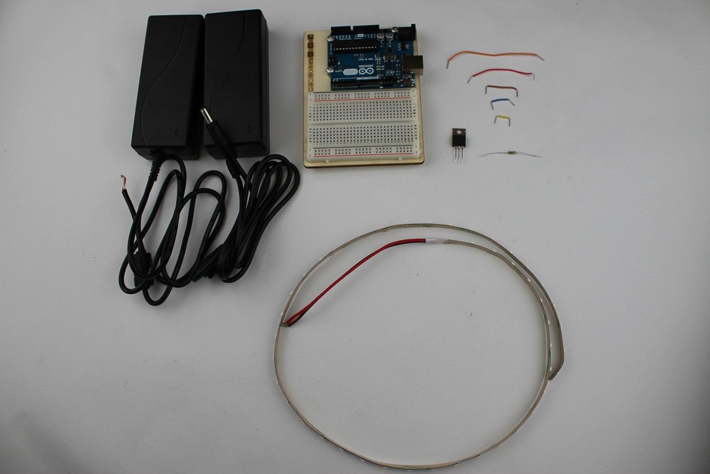
- 12 volt transformer with the wire stripped back revealing the copper strands on both the Plus and Negative wires
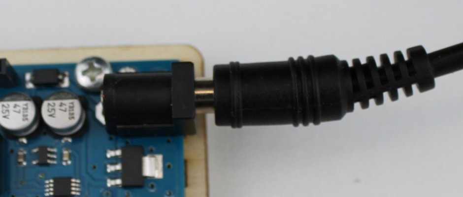
- 12 volt transformer with the power connector still present
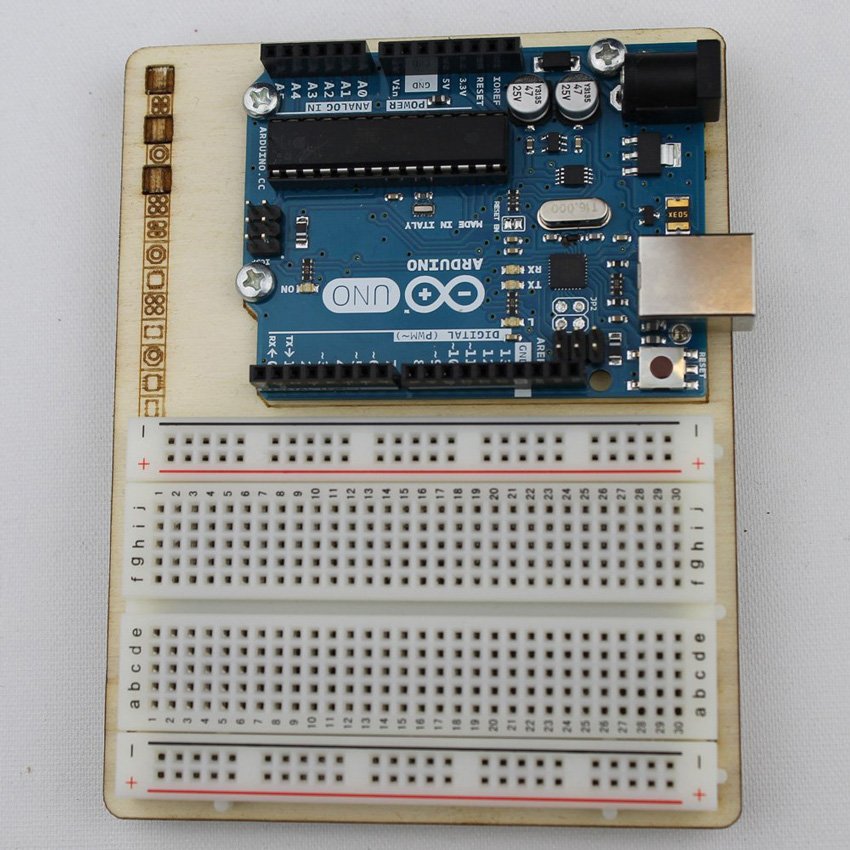
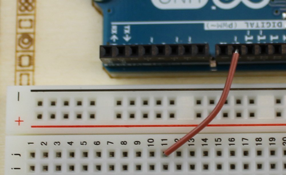
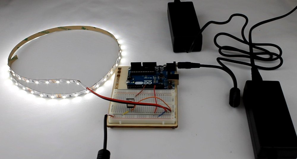
- Arduino Uno board
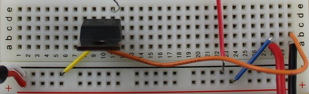
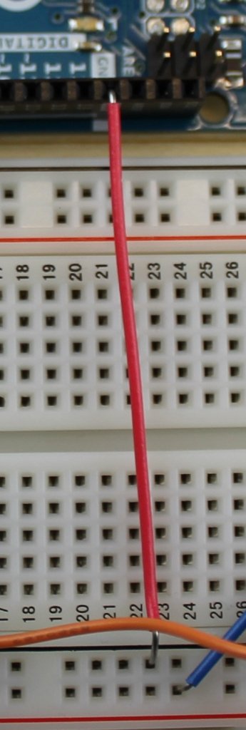
- Breadboard
- 5 Jumper Wires (various sizes)
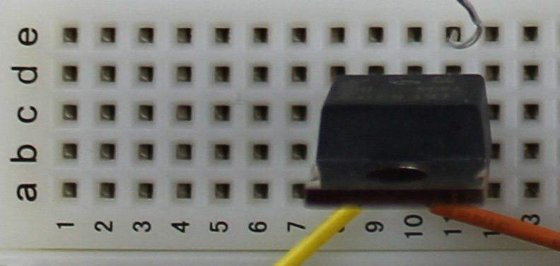
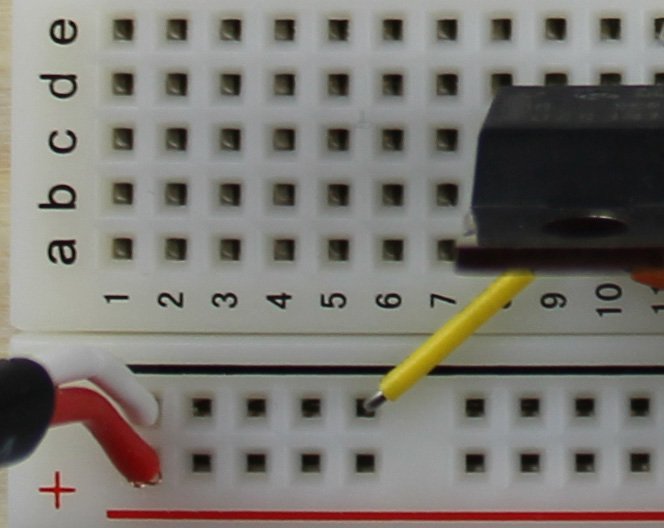
- 1 Transistor
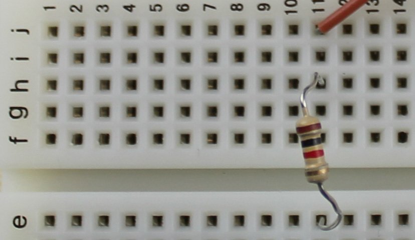
- 1 Resistor
- LED Tape
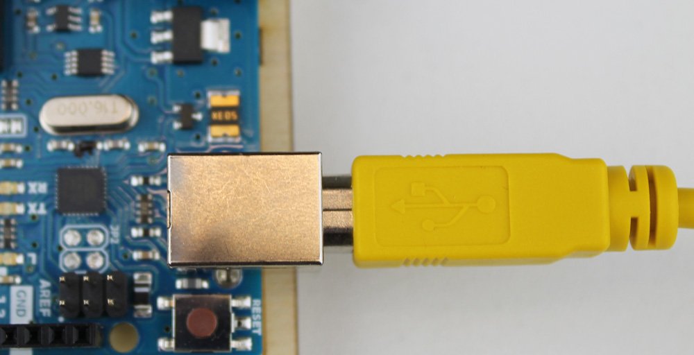
- USB Cable


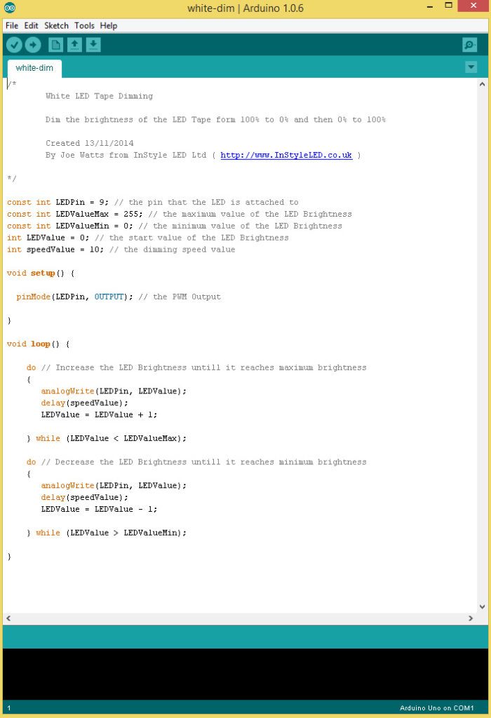
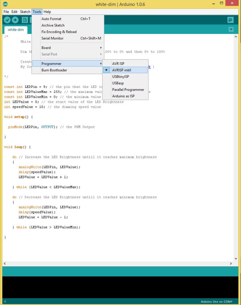
White LED Tape Dimming
Dim the brightness of the LED Tape form 100% to 0% and then 0% to 100%
Created 13/11/2014
By Joe Watts from InStyle LED Ltd (www.InStyleLED.co.uk)
*/
const int LEDPin = 9; // the pin that the LED is attached to
const int LEDValueMax = 255; // the maximum value of the LED Brightness
const int LEDValueMin = 0; // the minimum value of the LED Brightness
int LEDValue = 0; // the start value of the LED Brightness
int speedValue = 10; // the dimming speed value
void setup() {
pinMode(LEDPin, OUTPUT); // the PWM Output
}
void loop() {
do // Increase the LED Brightness untill it reaches maximum brightness
{
analogWrite(LEDPin, LEDValue);
delay(speedValue);
LEDValue = LEDValue + 1;
} while (LEDValue < LEDValueMax); do // Decrease the LED Brightness untill it reaches minimum brightness { analogWrite(LEDPin, LEDValue); delay(speedValue); LEDValue = LEDValue - 1; } while (LEDValue > LEDValueMin);
}


To have the LED Tape flashing you use this code:
White LED Tape Blinking
Turn the LED Tape on and off at a chosen speed
Created 13/11/2014
By Joe Watts from InStyle LED Ltd (www.InStyleLED.co.uk)
*/
const int LEDPin = 9; // the pin that the LED is attached to
int ledValueMax = 255; // the maximum value of the LED Brightness
int ledValueMin = 0; // the minimum value of the LED Brightness
int blinkSpeed = 10000; // the blink speed in milliseconds
void setup() {
pinMode(LEDPin, OUTPUT); // the PWM Output
}
void loop() {
analogWrite(LEDPin, ledValueMax); // Turn LED To maximum brightness
delay(blinkSpeed);
analogWrite(LEDPin, ledValueMin); // Turn LED To minimum brightness
delay(blinkSpeed);
}
